Cable Ploughing
European Cable Ploughing Specialists
Introduction
Distribution of cable utility services is accomplished using two general systems: Overhead and underground cable. Gas, Water and Sewer have historically used the underground technique. Telephone, Cable TV, Electrical Services, and now Fibre Optics are often being specified for underground installations. This trend is due to the development of new materials and technology in cable types and construction as well as the obvious protection from the elements.
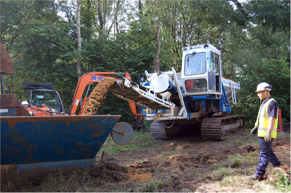
Installing underground cable utilities has usually been undertaken by traditional open cut method, chain trenching or directional drilling. Early cable ploughing was accomplished by pulling a ripper blade with a cable laying chute attached onto the back of the blade through the ground using brute force. This often required connecting several crawler tractors together to get enough draw pull. This configuration often tore up the work site and required substantial restoration in addition to involving multiple pieces of equipment. However, this method was usually more economical than opening a trench, installing the utility, and restoring to original site condition.
In the past 12-16 years the method of applying vibration to the ripper blade has become more advantageous. By shaking the blade, usually up and down, the soil will cut easier thus requiring less force to pull the blade.
Cable Ploughing Conditions:
| Soil Type |
Description |
Ploughing |
| Sandy |
Loose and granular soil, individual grains can be seen |
Excellent |
| Clay |
Fine textured soil which forms hard lumps or clods when dry |
Excellent |
| Loam |
Having a relatively even mix of sand, silt and clay |
Good |
| Stony |
Any of above types with a considerable amount of pebbles |
Fair |
Cable ploughing performance is effected by certain factors i.e.; A high clay content will allow easier cable ploughing because of the high moisture content, durability and ease of movement. Moisture loosens the soil and acts as a lubricant, allowing the shank to cut through a lot easier. Soil compaction relates to how much air and moisture is mixed into the soil. Highly compacted soil such as found under a gravelled road will require more force to cut through.
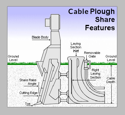
| Shank/Share Part |
Description |
| Blade Body |
The main backbone of the plough shank, usually made from high strength dropped steel with a high abrasion resistance |
| Shank/Share Rake Angle |
The amount of angle the shank cutting edge lays back from vertical |
| Cutting Edge |
The leading edge of the shank body which does the soil cutting. Usually wears to a dull point and with added hard surface welds, this will extend the shank life |
| Toe |
Lowest and most forward part of the share body |
| Cable Chute / Laying Section |
Attached to the trailing edge of the shank body into which cable or others is installed |
| Removable Cable Ribs / Gate |
The Ribs are Installed into the back of the laying section which allows easy feeding of the cable through the laying section this alleviates the tension pulled through the cable chute |
| Radius |
The Minimum bending radius of the cable to be installed |
| Cable Depth |
The discharge location of the laying section is determined by toe depth, It is generally several centimeters above the toe depth. |
| Each of the above mentioned shank components has an effect on how well the shank will perform in given soil conditions. The following is a description of how each will affect productivity. |
| Shank/Share Part |
Effect on Ploughing Performance |
| Shank/Share Body |
The thicker the body material the more force is required to pull it through the soil. Thin shank blades pull easier. Depending on the width of the laying section, different size cutting blades can be fixed on to the front edge of the shank |
| Shank/Share Rake Angle |
The closer to vertical the cutting edge, the more tendency a share will have to coming out of the ground as it is being pulled. The more laid back the angle the more a share will pull down into the ground |
| Cutting Edge |
As the cutting edge becomes blunt, the more force and horse power is required to pull the plough/shank through the ground. Hard surfacing welds to the cutting edge will extend the life of the cutting edge and shank |
| Toe |
The size, width and mounting angle of the toe all effect whether a shank cuts easier and dictates the cable chute size. |
| Cable Chute / Laying Section |
Wider laying sections to accommodate larger diameter cable pull harder than narrow sections for smaller cable |
| Radius |
Larger diameter cable generally requires minimum bending radius. The larger the bending radius, the longer the cable curve radius required. Larger cable chute/laying section length causes more side surface area to drag through
the soil requiring more draw pull force. Smaller cable chutes and bend radius generally pull easier through the ground. |
| Cable Depth |
The deeper the ploughing depth the larger the draw bar required. Generally, installing cable 170cm depth requires more than twice the draw bar pull than to install cable at 75cm deep |
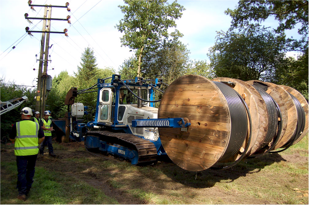
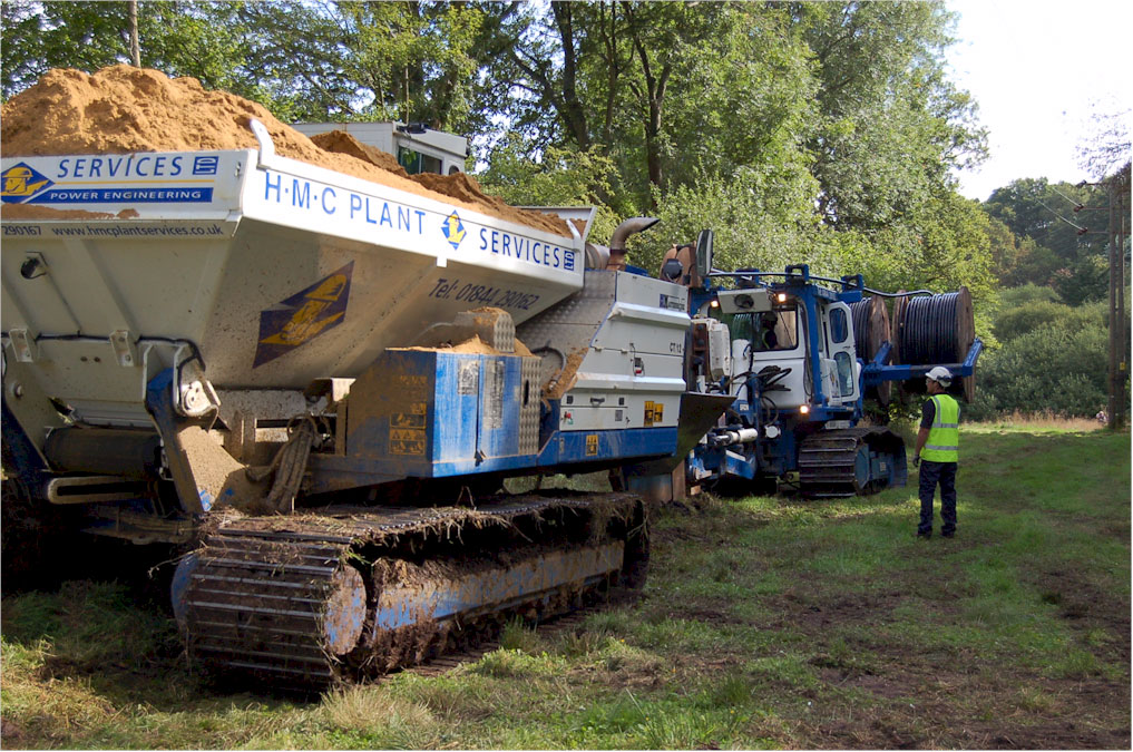
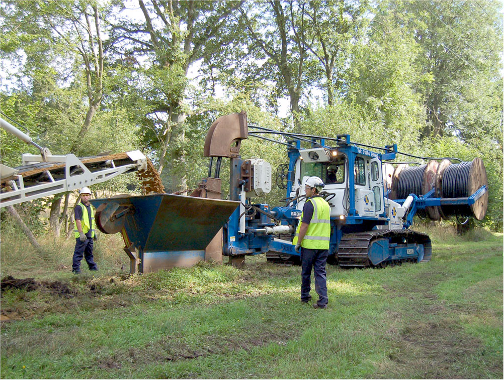
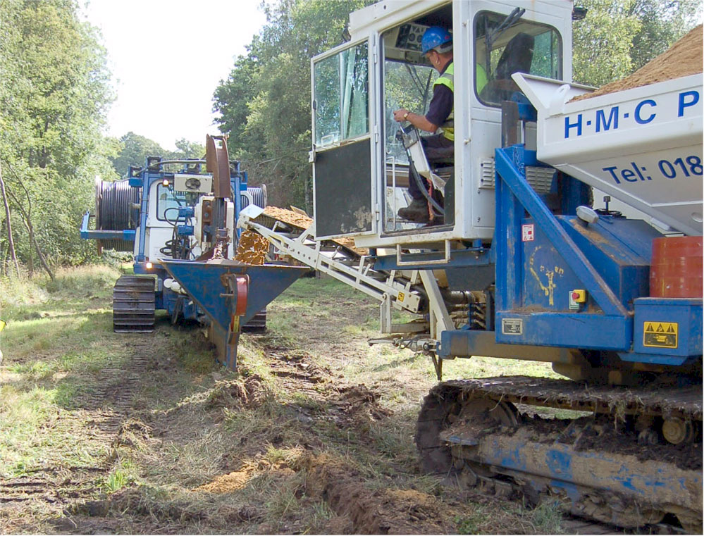
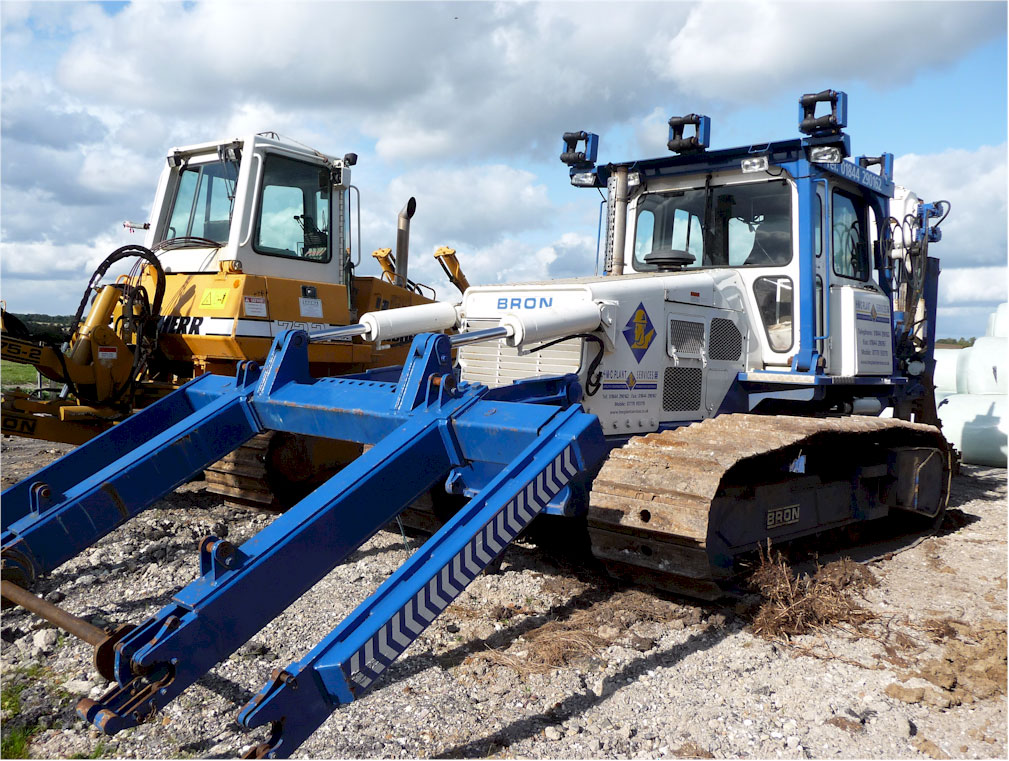
| The unique cable chute / sanding hopper and plough shank design is only available to our cable plough design. The sanding chute and cable laying section allows the shank assembly to hinge on the front of the cable chute, this allows the cable to be drawn around shallow bends and corners. The sand or finefill hopper provides added protection for delicate cable such as Fibre Optic, Plastic Pipes, Pipes for Water / Gas Industries and low voltage / high voltage electric power cable. |
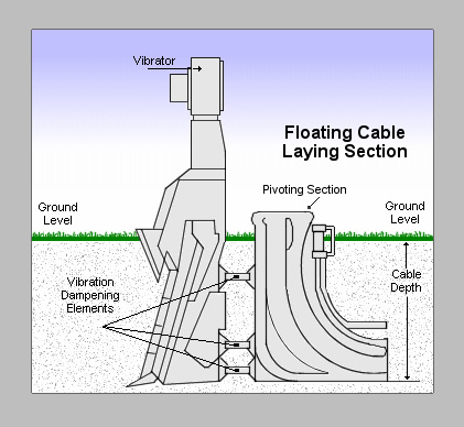
Cable Vibrator:
The last major component which affects cable plough productivity is the speed and amount of vibration that is applied to the shank / share blade. The vibrator consists of counter-rotating eccentric weights. The faster the weights rotate, the more force they produce. The benefit of cable vibratory ploughing over static cable ploughing is that with the help of the vibratory force, the toe and cutting edge of the shank / share lift fracture the soil before the shank body and laying section are pulled through by the crawler. When ground conditions are dry or high compaction exists, high speed and force is required to break up the soil. As the operator can adjust the vibrator from inside the comfort of the cab, he can concentrate on the cable ploughing force rather than the cable plough speed. The harder the ground the slower the cable ploughing speed will be. If the ground conditions are soft the operator can accelerate the speed to optimise the performance given by the cable plough.
Cable Turf Cutter:
When cable ploughing conditions are established in grassland or crop conditions where shallow roots exist, the addition of a turf cutter attachment is advised to once again minimise ground disturbance and restoration. The design of the cutting edge of the turf cutting blade will cut separated grass and roots in a down cutting motion which then allows the cable plough shank blade to pass without snagging the roots and pulling them up to the surface.
Cable Plough Offset:
Many job sites require installing a utility close to an obstruction (building, fence line etc). To accomplish this, the cable plough can swing to the side of the machine and steer the cable plough shank blade in the direction of travel. This offsets the machine from the cable plough shank and allows the machine to pass by the obstruction. This feature also makes cable ploughing around corners much easier.
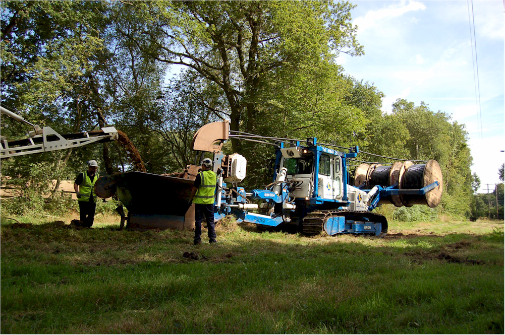
More Cable Plough Features:
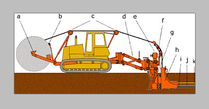
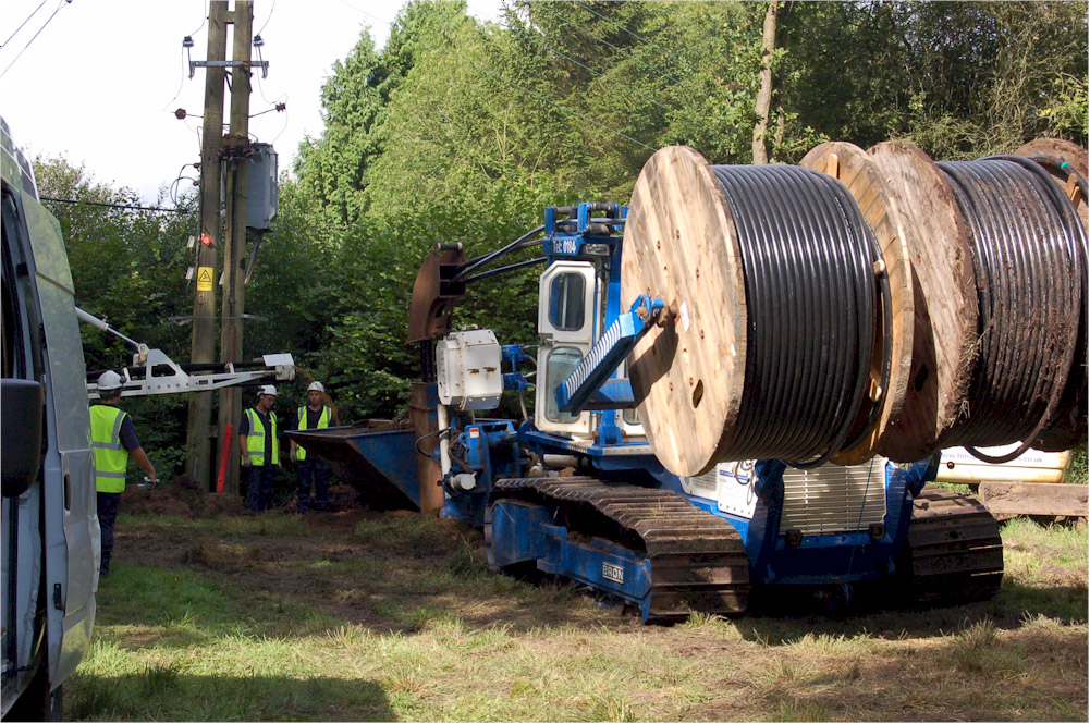
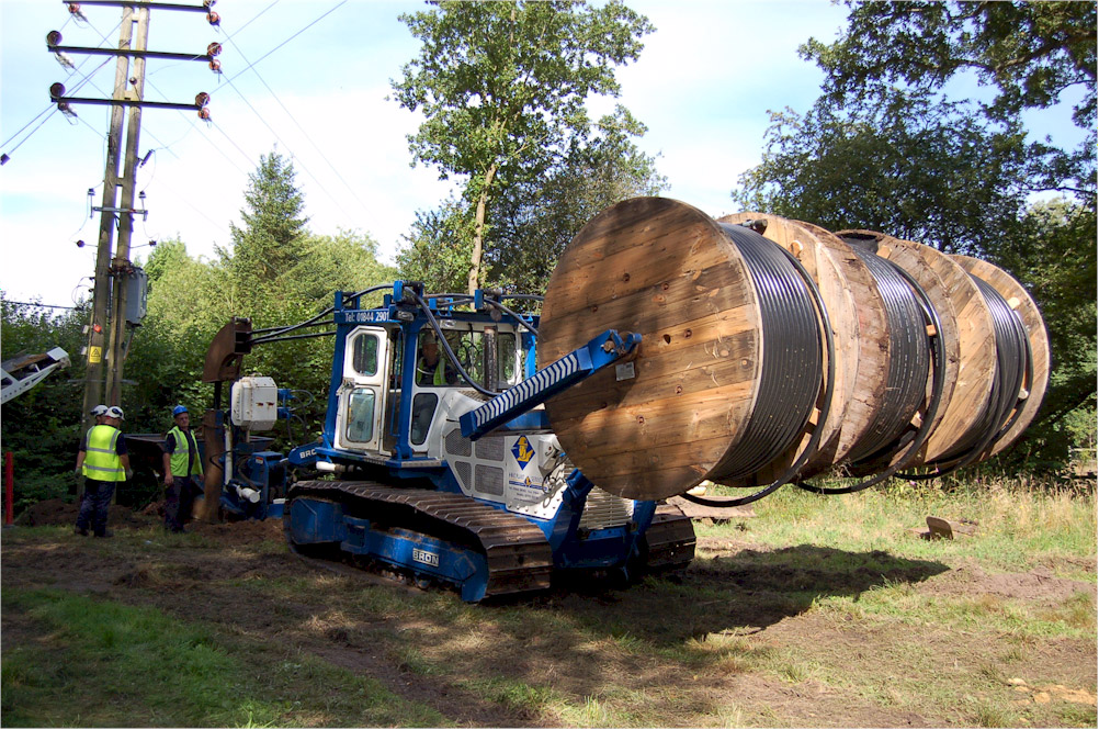
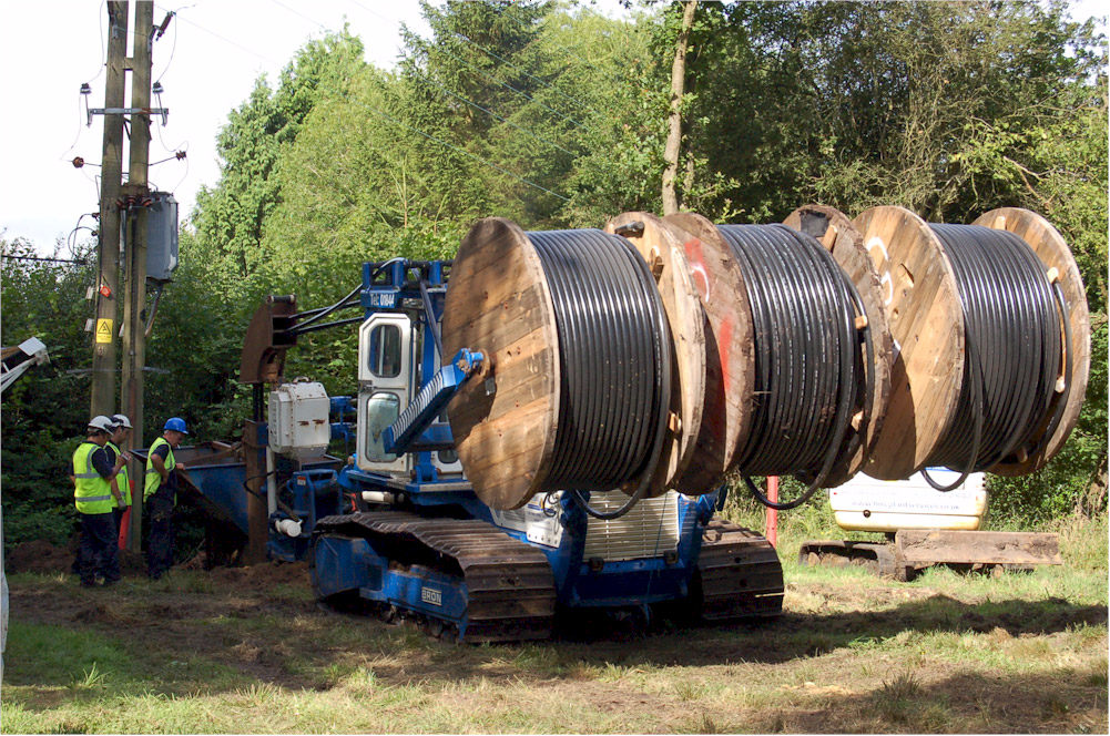
a) Drum mounting b) Drum brake c) Guide roller d) Lifting mechanism e) Vibrator f) Roller quadrant g) Cable Plough share h) Cable-laying section i) Cable or duct j) Screening conductor k) hazard-warning
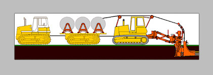
This fitment will undertake our 132KV cable installations, the cable drums can weigh up to 11 tonne each hence the separate drum trailer formation. The cable plough will be A D10 or Leibherr 764 size.
Jobs Completed:
2015 Plough Schemes
- 8km Ludlow 33kV Single Circuit
- 3.5km Weir Hill 33kV Dual
- 14km Gloucester Water Installation
- 4.1km Mid Counties Solar Field
Up To End of 2014
- 11kV 475km installed
- 33kV 285km installed
- Fibre Optic 40km installed
- Water Installation 75km installed